1/11/2019: An interesting evening spent in the garage last night. Some of the bits I had ordered arrived and I decided to spend a little time assembling them into something.
The components were a clear acrylic tube 7mm ID and 10mm OD. I was going for something that would not suffer from eddy currents and potentially an IR interrupter could be used to track the progress of the projectile.
The projectile is a 50mm long screwdriver bit with the tops of the hex ground off. These were end of line from screwfix at 29p for 3 so I got 6 as that was all that was available to me locally.
I had some 1mm enamelled wire so I 3D printed a former to wrap it onto. This bore a strong resemblance to a large cotton reel with a 10.2mm bore, 12mm OD and a couple of ends with facility to bring the wire out. The length of the coil was guessed at from other sites that said about projectile length +33% worked well.
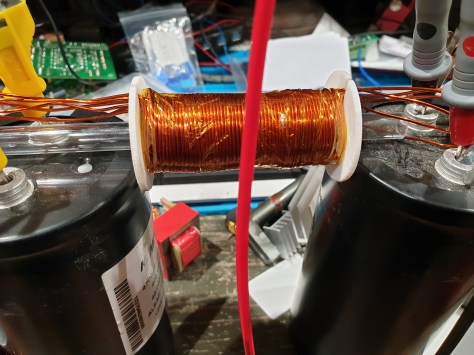
I created this coil with two slots in the ends, the plan was to bring out each layer into a tap so I could investigate the effects of changing the number of layers and therefore the resistance and inductance of the coil. Couple this with the ability to increase the voltage to over 500v then there is plenty of room for experimentation.
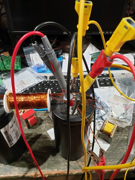
It took a while and several episodes of cramp to wind the five layers onto the former. Initially I simply used one capacitor (4700uF 400v) running at 35v (the best my bench supply could do) to power the setup.
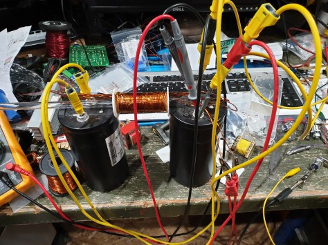
I used a vs-50ria100 SCR to switch the current through the coil after disconnecting the power supply. My first results with one capacitor were encouraging and under whelming at the same time. Encouraging as the projectile moved and nothing went bang or silently stopped working. Disappointing as the projectile only went about three inches maximum in the tube. All my target boxes were safe for the moment. Add another capacitor though and things definitely improved however as you can see on the video below.
H&S may have kittens if they saw this:
I thought though running at 35v I was in more danger of a frightening spark than a lethal shock. This will change though so I am going to build something I can stay well away from during operation!
Ok, next steps: Now I have a proof of concept going I need to create a more repeatable setup with some room for expansion. To this end I am going to create an Arduino powered control system. This will consist of an Arduino, a touch screen from 4D systems as these are easy to develop quickly and some control electronics. These will consist of a relay to disconnect the power source and an opto isolated transistor to drive the gate on the SCR. Initially I just touched a wire to the gate terminal which was not wise as it has a 20v limit and I was on 35v. Never mind, it still works.
The power will come from a variac and a 230 to 400v transformer through a bridge rectifier. I’ll also setup the system somewhere a little less crowded as in front of my keyboard is not the best position
