This was bought in September of 2017 as a project. As a lathe it was pretty useless as the school it had come from had kept the computer and software so all that worked was the manual controls. All you could really use it for was to polish something you put in the chuck, not very useful.
Over the next few months this will hopefully grow all new electronics and be able to interface to Mach3.
I decided very early on that I needed threading capability on this lathe. After a lot of research one of the key factors I needed to consider was motor control. I spent a lot of time looking at various inverters and variable frequency drives (VFD) which control three phase motors. In addition to this I would need an index pulse so any threading action had a consistent start point. I had gained a little experience with speed control when I added exactly this functionality to my Clarke mill and it was not entirely satisfactory. Not a problem on the mill but could be better for a lathe. To cut a long research task short I decided on a Delta drive, the VFD022V23A-2 along with the PG-02 pulse generator interface card. These were ordered in early October 2017 but are likely to take a month or so to be delivered.
Ok, here we are in mid October and my plans have already changed. The above Delta vfd is now destined for the mill as its supposed ability to consistently stop the spindle in a known place will be invaluable for my auto tool changer plans.
I do however have the lathe in a position in the garage where I can now get to both sides, well, front and back really. I have had a bit of a sniff round and as expected it is running a 3hp 3 phase motor off an ancient vfd. It all works though so I’ll try and use it until I can’t. Next job is to try and map all the inputs and outputs and in particularly the safety circuits.
13/11/2017: A few weeks ago I ordered a pair of closed loop 8Nm stepper motors off eBay and they have now been delivered. I bench tested them and whilst they are nice and smooth their speed was rather underwhelming. Dead easy to wire up and get running from mach3 though. This set me thinking about what I wanted from this and the milling machine projects. Surprisingly possibly, I decided it was the journey and people knowing about it via this site etc. which is important. I don’t have a use for the machines yet although I am sure I will think of something.
Anyway, this revelation led me to consider the end result and to that end I went back to my servo thoughts. Initially I had binned this as it was very expensive but I am now up for the technical challenge. This wasn’t helped by the fact that Zapp Automation have 15% off for a couple of weeks. So, I now have a single servo to play with along with some other goodies.
24/11/2017: Black Friday as it is becoming known…… Very black for my poor old bank balance.
I took the plunge today, nearly £400 quid saved in the Zapp Automation sale, just had to spend a lot to get that. Coming to a garage near me soon though I have another CSMIO controller, three more servo motors and associated components and finally an mpg wheel and the module to plug it into. I did a bit of measuring before ordering and I know I have some challenges to overcome. Examples include losing an inch off the x axis travel towards the motor as the new one is longer and some cable routing challenges as the new ones are thicker than the originals. Never mind, one hurdle at a time.
I have connected the existing motor controller to the PC and read a load of parameters. The only down side is at the moment I don’t understand what I am looking at so some more reading to go. I’m hoping to get some time over Xmas but we’ll see.
4/1/2018: I have spent quite a long time picking over the electronics in the lathe and have finally made a decision on how to proceed in its renovation. I have used stepper motors before on my Clarke mill so I thought the challenge of working with servos sounded interesting. To this end I have ordered servos (as above) for the main axes on both the mill and the lathe. I intend to remain with steppers for the turret on the lathe and the z axis or up and down on the mill. Neither of these two benefit vastly from servo drives and I already have suitable closed loop servos for both. Anyway, quite a long wait for delivery now hence the photography exploits elsewhere on my site. This is sort of linked as I am using a servo there too.
4/2/2018: Some more of the parts for the conversion have arrived so I thought I would have a little play with working out some more of the wiring. All was going OK until it wasn’t! All manual control was fine and I was looking at the z axis limit switches. Suddenly I could only move towards the chuck and the spindle no longer turned under power. Some poking around didn’t really solve the problem however it seems from the symptoms that the z axis limit switch has failed in the tripped state. Coupled with a firm suspicion that the switch at the other end of the axis has also failed maybe I should look into replacing all of them as most will be original hence over 20 years old.
I also stripped the drive for the z axis which had an unusual although effective way of locking the drive to the shaft. It is threaded and there is a lock nut with 3 bolts through it. It threads up close but not touching and the bolts then pull the two threaded elements together locking it to the shaft. Effective when you cannot hold the shaft or the pulley easily. Off to try and find new pulleys to suit the servo and the 12mm shaft.
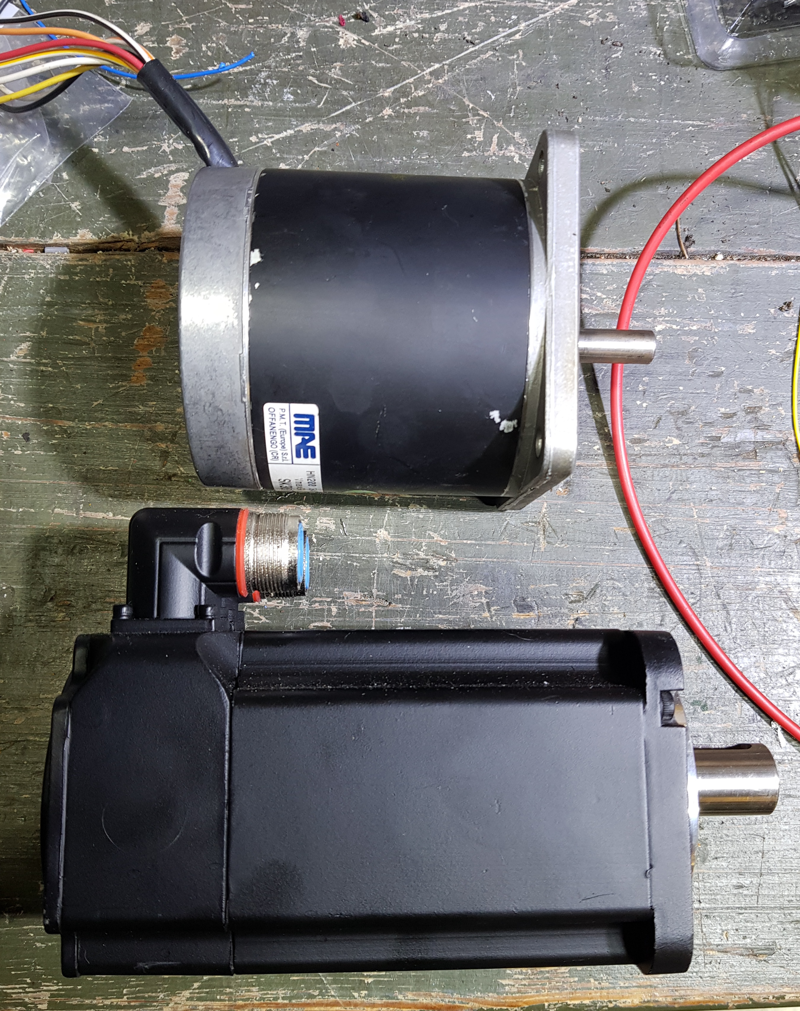
11/4/2018: Here are some photos of the steppers that are coming off the lathe and the servos that are replacing them. As you can see there is a significant length difference although the diameters are similar. Another point worth noting is the shaft diameters. The original stepper is a tiny shaft approximately 10mm whereas the servos are 19mm. Unfortunately the mounting holes do not align well either however there is probably some leeway to re drill the mounting plate to fit.
These are the labels on the old and new Z axis drive systems


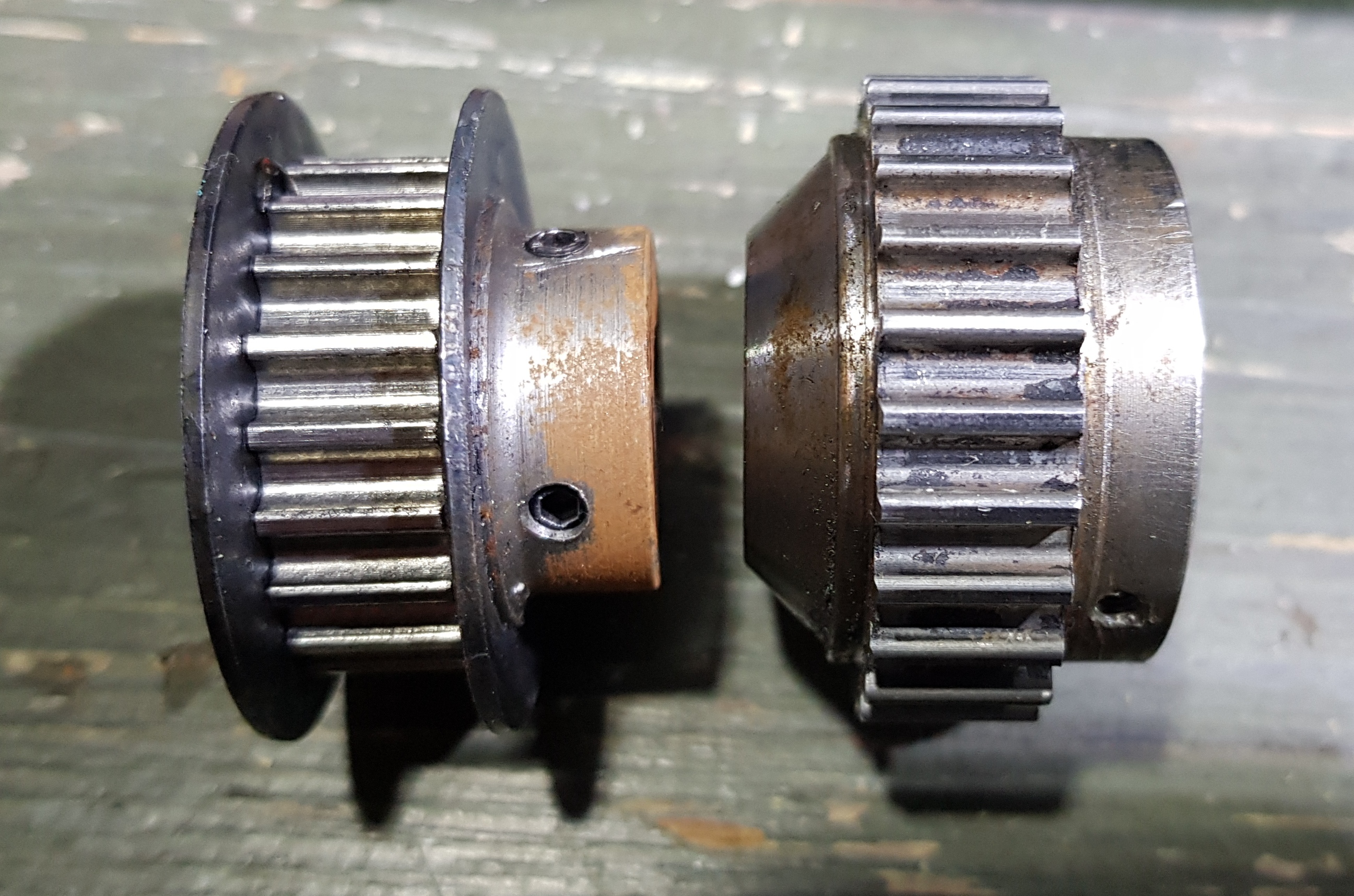
Here we can see the original drive pulleys for the Z axis (left is from the stepper and the lock mechanism for the right pulley is not shown). They are of a very similar size giving a close to 1:1 drive ratio. Steppers rotate much more slowly than servos and the recommendation is a 3:1 ratio for the new servo drive. I will have to have new pulleys made as neither of these is reusable even with machining. The one on the left can be a similar size but just needs more material for a key-way, the one on the right needs to be about three times its current diameter.
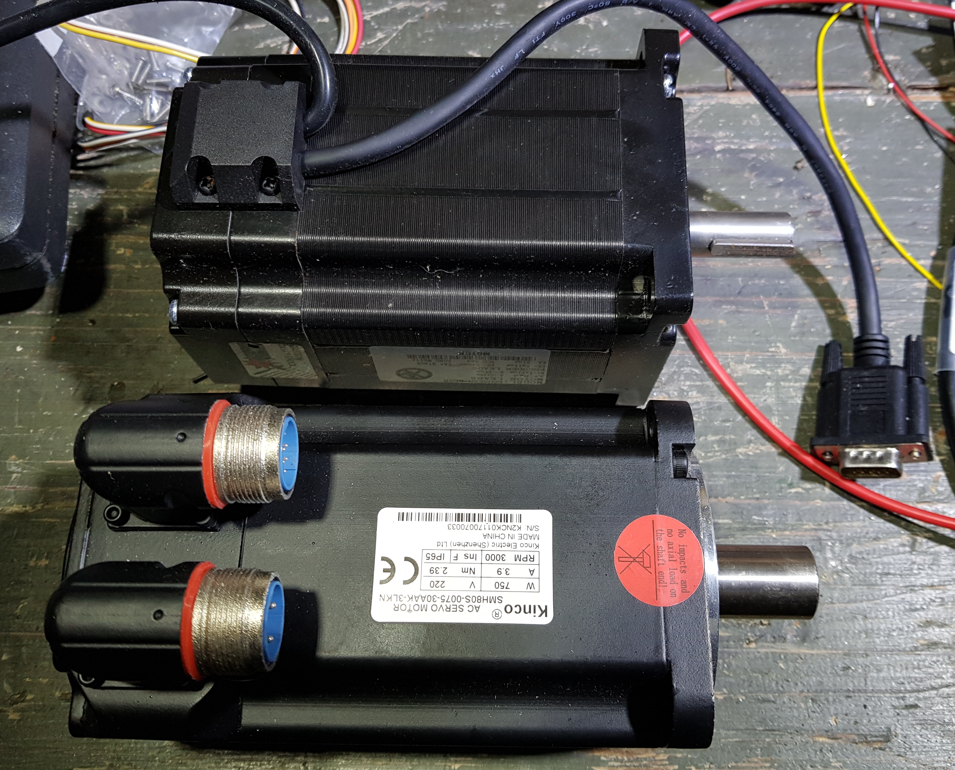
Here we have the new servo alongside the new closed loop stepper. In testing I was very disappointed with the performance of the closed loop stepper. It was smooth enough but stalled out far earlier than I was expecting prompting my move to servos for the main movement axes. Shaft size on the stepper is half way between the original and the servo. It should be fine for non speed critical stuff though so I hope to be able to use it on the turret. If not, in the short term I will reuse the original stepper and get a new driver for it.
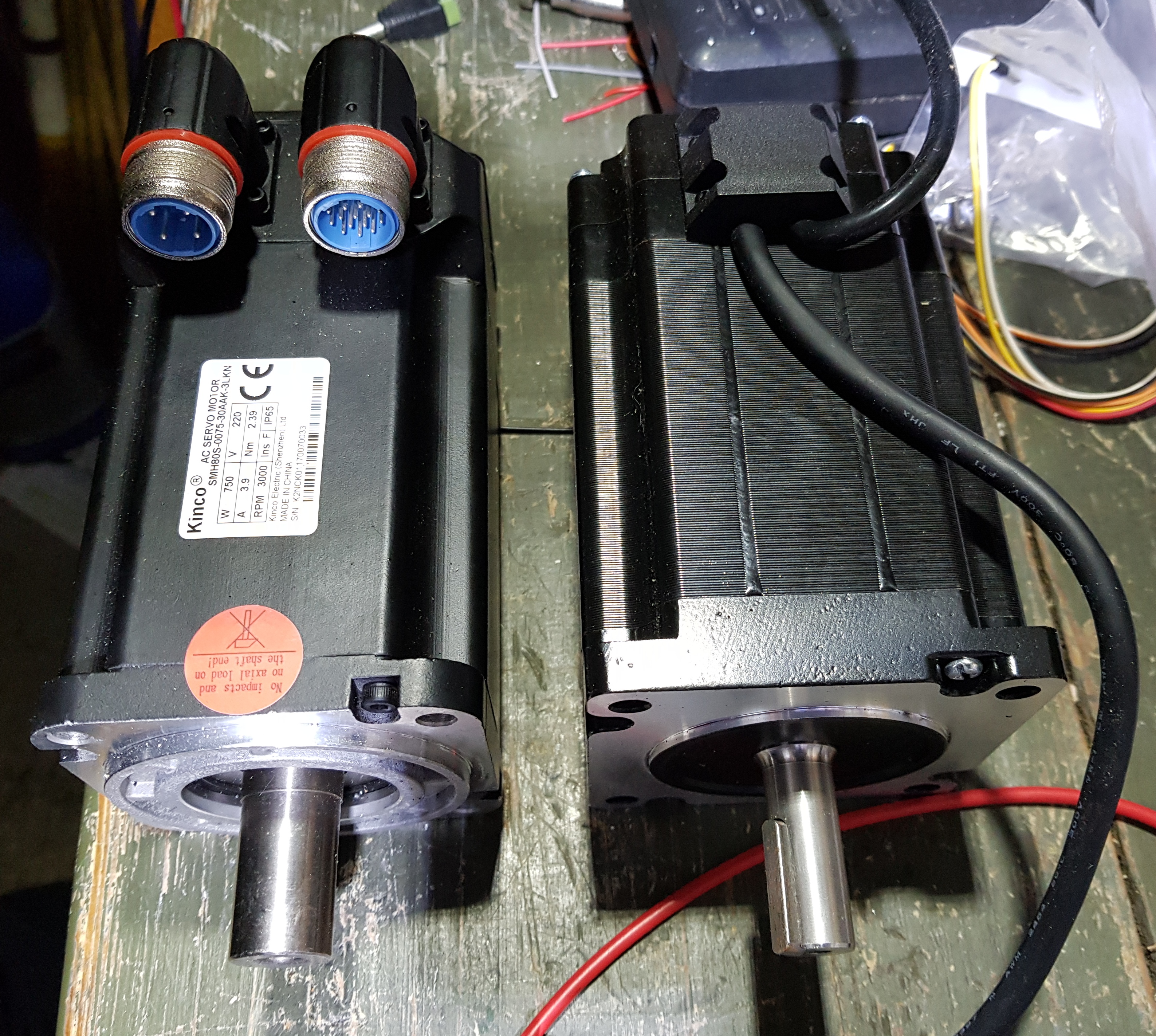
And finally a picture of the servo and new stepper side by side. The stepper was bought from Ebay shipped from Germany for a very sensible price i.e. fairly cheap. The servo was bought from a UK company Zapp Automation. It is an industrial grade piece of kit hugely over specified for the use I am going to put it to and it also has a hefty price tag including the drive unit. I am very hopeful however that its performance will be orders of magnitude better than a stepper based equivalent.
To summarise: originally steppers were fitted to all axes. I am replacing the main X and Z axes drives with AC 240v servos. The turret or Y axis will stay some sort of stepper drive, either a closed loop one as shown if I can shoehorn it in (and I have one) or the original plus a new driver.
31/5/2019: Well, not much happening with the lathe at the moment but this is because I need to make some custom brackets and modify the pulleys I have bought. For this I need a Mill or pay someone to do it all for me. I chose the former as I have one sitting here waiting for a Mach3 conversion. This is progressing slowly and progress is logged on the VMC300 page. It is proving quite fun though and I am making steady progress.
17/2/2021: Here we are in 2021, Covid is well underway and I have made a lot of progress on various electronic projects as well as the VMC300 mill. The mill story is in the associated page but the summary is that it is working under Mach4 but awaiting some finishing electronic pieces. Roll on the PCB from JLCPCB to see if I got it right this time.
Anyway, back to the lathe. All my grand plans for servos are on hold and the new plan is to use the original steppers with new drivers (DM860’s are on the shelf) and a CSMIO/IP-S. I have mostly put the steppers back in and stripped out the old drivers. Next step is to revisit the wiring and voltages etc. I’m hoping my experience with the mill will help but we’ll see.
Sadly I’m working pretty much all the time till Easter now so progress will be slow but anything is likely to be faster than of late.
5/4/2021: Yippee, Easter is here and finally some time to play in the garage. It has been interesting to say the least. I have pulled all the old wiring to pieces and now know where 98% of it goes plus I’m pretty sure I don’t care about that last two percent.
I ripped out all the old stepper drivers and repurposed their mounting frame minus the printed circuit boards etc. for the new drivers. These actually mounted rather well and are nicely spread out above the original fan which I have left in for the moment. The drivers have their own fans but you cannot be too cool!
I am reusing the original huge transformer to power the steppers and also the baby transformer which does the lamp. I could replace them but why bother if they are working well. So, bar a little shortening of wires and a tidy up the bottom cabinet is done.


The top cabinet is a mess of wiring at the moment but that’s ok, give me time.

I have been playing with the various motors though and after a bit of tuning have all of them functioning. I had to trick the system to prove the tool changer worked because there are no built in controls being a lathe. At some time in the future I will have to write a macro to do this for me. Here are the three of them in action though.
I have had some interesting thoughts though. I like manual controls and buttons and switches etc. so I will be adding these to my new front panel. Largely they will replicate the original ones however there will be some nice additions.
I have also found out that the original encoder wheel will not cut it in the new world. Things have moved on rather and instead of the old 50 ident and one index mark via optical trigger I now need an incremental encoder with a full differential interface. To make matters harder the original wheel is about 6 inches across and has the bar feed going through the middle. All the modern encoders won’t fit this design easily so I am considering rolling my own. I’m still looking into this as it sounds interesting but it may ultimately be easier to gear an off the shelf unit in somehow. If you have any thoughts or ideas then send them my way.
It would also be nice for the controller to know which is the currently selected tool so it can make intelligent decisions about selection that don’t depend on me. This will be interesting to solve for sure
So, summary to date:
- All motors and drivers fitted and working under manual control
- Wiring understood and partially modified
- Safety circuits for the spindle working but not connected or programmed yet
- Emergency stop working and wired into the controller
- Pretty much every limit switch has chosen now to go on the blink so I have to remove them and source replacements. Naturally they are a pain to get to but I like the idea of homing it after use, brings back memories when I used to run one of the things in a real workshop
- Spindle has been scratched but nothing decided yet
6/4/2021: OK, apparently being cool is good however the noise of the original fan was considerable so I have disconnected it. Joy…
18/4/2021: A very happy hour spent nibbling away at the lathe limit switches last night. For a long time now a single black proximity sensor wire disappearing into the end of the Z axis slide has had me baffled.

I had looked all around for it using an endoscope type camera, phone photos, hanging my head into the swarf tray etc. all to no avail.
Anyway, last night I chose to solve this and removed the end drive to see if it was in there somewhere. It turns it isn’t……

So, I started looking elsewhere and eventually found it. The wire went through a drilling and emerged out the bottom and then headed to the X axis. It was hiding under a shiny trim and was the X axis homing limit switch.


I cleaned it up and tested it, all fine. It’s now all connected and set up in Mach4.
20/04/2021: It’s been a busy time recently but I have managed to make a lot of progress. Tonights win was persuading the spindle into life. It’s very jury rigged with all the control relays held in the correct positions with crocodile clipped wires to earth etc. but, hey, it works.
The original Boxford electronics had the dc 0v rail tied to earth. In the modern world this is not a good idea so I had to work out how it all worked and make the necessary changes. As it transpired this meant a couple of changes to the direction inputs, rewire the logic common (analogue ground) and that was it. Fighting with Mach4 took just as long but once I remembered the relevant screen it all fell into place. Luckily I had already wired everything else to match so no additional changes needed.
I’ve still got the tool changer Mach4 macro to crack and then the considerable task of adding manual controls but there is light at the end of the tunnel 😁
21/04/2021: A bit of a tidy up session tonight. I wired in all the jury rigged relays etc. to the outputs. This didn’t go as smoothly as expected as they were wired switching the earth and the csmio controller sources 24v instead. A quick shuffle round and it was all sorted. So far so good and I have both forward and reverse on the spindle and coolant control. I’m now neatening up the remaining wiring for the limit sensors etc. which of course will need testing when complete.
8/5/2021: Things are looking good now. I have neatened everything up and it all still worked so that was a bonus. I then started thinking about the manual interface which presented some questions I need to think about so I started thinking about the 8 position tool turret. After quite a few hours researching I realised I was mostly on my own. The m6 macro which does all the work is normally written by the manufacturer / supplier of the machine – darn, that’s me. A lot of research later and a couple of days playing and I have a working m6 macro which will set the tool to the requested one from any position. I have also added buttons and a tab to Mach4 to allow manual control.
One caveat at the moment is the machine needs to have tool 1 selected when it thinks it is at tool 1. Kinda obvious I guess but it is a manual step which the soft squidgy bit may forget one day. I’m now thinking of adding an index sensor and writing a custom home script for the tool changer which will set it up correctly. This is a future development though as there are bigger fish to fry in the short term.
If anyone wants a copy of the current m6 / m06 macro just drop me a line via the contact form. I will post details of it once it is complete however no guarantee when this might be done.
2/6/2021: Not much time for garage therapy at the moment but I have been researching threading and in particular the spindle encoder that is needed. I have been down all the roads I think, DIY optical, magnetic, various ppi readings and of course different output types. Research tells me that for my hardware (csmio/ip-s) the ideal solution is 10000ppi with differential outputs for A, B and Z.
Roll on quite a long time and some heart stopping prices and I believe a Sick DFS60 unit will suffice. These are just over £300 from RS Components. Ohhh, if that was it. It is a programmable unit so if its default settings are not what you need there is the cost of the programmer and cable which could be another £200.
Maybe though….. EBay to the rescue. I managed to win a new item (old stock) but it doesn’t have any cables or anything. I’m waiting on its arrival to see if this gamble works. If it does I should have a complete unit for around £70 once I have made a cable, winner. After this I’ll have to work on a way of fitting it
12/6/2021: Not much time spent in the workshop but some good progress made.
The ebay encoder has arrived as well as the connector from RS. I have temporarily wired it up so I can test it on my scope. I only checked the signals independently but I’m happy to have got what looks like strong differential outputs. I have also come up with a mounting plan and therefore ordered the pulleys and belt. One will fit directly onto the encoder but I will need to machine the other to fit the spindle. More thoughts there when it arrives in a couple of weeks.
I have also been working on the manual controls and specifically the pendant (mpg). I am using the csmio mpg module but not their mpg unit. It was a bit of a fight but success was achieved with only a couple of challenging moments.
Next is manual spindle control and overrides e.g. feed rate etc. Once I have this working I essentially have an electronically controlled manual lathe. Better keep going I guess otherwise I might as well of bought a basic manual lathe.
Still lots of real work to do over the next couple of months so no huge leaps forward expected but I will no doubt keep nibbling at it. We are on the home straight though for sure
More soon
Here is a document I have been keeping as I delve into this project. It contains a lot of thoughts and unfinished work however there is some pretty good stuff in there too so enjoy. Don’t forget the wiring on mine might not be there same as yours so check before poking your fingers in and particularly where voltages are concerned.
