Detailed notes on this conversion are available in the downloadable document. Note this is about 50 Meg at the time of writing and only covers the VMC to Mach4 conversion so far. This is not complete and changes every now and again as I upload it
5/5/2019: Hmmm, okay, it seems I have made a bit of an error in judgement and ended up with two of these machines. The first was bought with the lathe back in late 2017 but has just sat there in the garage since. Then a month or so ago I found another machine which was fitted with an auto tool changer, this was the version I was after in the first place but there are not many around these days. Long story short and it arrived at its new home in late April 2019.
It was bought in a non working state as the PC hard drive had failed. It took some wizardry to fix but it seems mostly OK now. Unfortunately, even though it has been converted to Mach3 it is a very complicated conversion and is not particularly reliable in the short time I have been running it. It has two parallel ports connected as well as two USBs and a serial port. The main motion controller is a CNC4PC C11 board. The main IO from the front panel is handled by a Pokeys board and the PLC that does the tool changing I think is USB to serial. I have not traced the other connections yet.
Anyway, after some head scratching I hope to convert the original VMC300 to mach3, use it to make the brackets etc. I need and when the other two machines are completed I will sell it on. This conversion will be orthodox in that I will fit new electronics but keep the original steppers. Because the other mill is done this way I have a pattern to work from which should make it easier. I have an ESS (Ethernet Smooth Stepper) already and am now waiting on delivery of the 3 stepper motor drivers. When they get here I’ll be able to make some more progress.
I guess the first thing I should do is recreate some sort of wiring diagram for both machines and its mapping into Mach3 in the case of the converted one. There are a lot of wires though……..
31/5/2019: Well, we are making slow progress. I have removed the lower mounting area and associated electrics and electronics. This includes a transformer, capacitors, junctions, stepper drivers etc. I managed to frighten the life out of myself when I decided to check the capacitors were discharged. It had been over a month since I had last turned it on but even so it was still quite a crack when I shorted them. Anyway, part way through ripping the upper area to pieces now.
The stepper drivers have arrived and I had a breakout board which I annoyingly cannot put my hands on so am waiting on a replacement arriving. Plenty to do in the meantime though.
14/8/2019: Progress – things are happening. I have created a map of how things work and what is connected where and what I think it does. Over the past few months I have been nibbling away at this and have finally got close to the further powered testing phase. In summary I have the new stepper drivers connected to power, all the original relays etc. connected as well as the VFD. There is no SmoothStepper connection yet, more testing of the safety systems still to do. Anyway, mains applied and no bang so all good so far.
21/8/2019: Things are moving on nicely. The SmoothStepper and two breakout boards have been fitted, wired up and tested and so far so good. This has been the plan of attack so far
Action plan for the Boxford VMC300 :
Puzzle out most of the original wiring – done
Rip out the unnecessary stuff – done
Fit stepper drivers, power supply and wiring – done
Relocate 12v power supply – done
Basic power on test – done. Door interlock failure – I’m going to ignore this for the moment as it is actually useful that everything works with the door(s) open
Fit SmoothStepper and breakout boards – done
Add basic wiring e.g. Network connection, e-stop etc. – done
Wire up stepper motors and test – done
Tune motors a bit for speed and direction etc. – done
Connect and test the limit switches. 2 off forX & Y & 1 forZ (top) – done
Spindle control next
Start looking into wiring up and testing remaining sensors e.g. spindle stuff
I have also been setting up Mach3 as I go. Still uncertain as to whether to migrate to Mach4 or not, more playing I think
22/8/2019: A little more progress, the spindle is now running in its default direction. The only surprise was when I shut down Mach3 the spindle shot up to pretty much full speed. This was caused because the output port on the breakout board used as the PWM control shot up to 2v. The PWM to 0-10v board interpreted this as about 90% speed. Some head scratching needed here…….
The other bit of good news was the initial failure of the door hall effect interlock system turned out to be an adjustment issue. A quick tweak and the enable relay is now working as designed
26/8/2019: I have now solved the runaway spindle issue. It’s caused by the implementation of the parallel port standard which calls for a 1.2k pull up resistor on the output ports. When the SmoothStepper does not have control of the breakout board i.e. Mach3 is not connected to it then the port goes high. This sends 5v to the speed control board and hence the issue is explained. I have resolved this in two ways, belt and braces you might say. I installed a bank of opto controlled relays which are active high. This means I can use the fact one of the ports on the BOB goes high to turn on the relay which in turn grounds the PWM in line to the speed controller. 0v = no rotation – yippee. The second thing I did was to set the spindle enable line to be controlled by another of the relays. So far so good I think.
5/10/2019: BIG DECISIONS! Now I have tamed the basic motion of the mill using a standard breakout board and the SmoothStepper I have been looking into my manual control requirements. Essentially I want the option of being able to control the mill for silly little jobs which I actually have quite a lot of. This means basic control of the spindle speed and maybe direction. Axis x, y and z control at rapid traverse and feeding speeds. I would also like to reuse the original control panel. To achieve this I will need to use the optional extra inputs on ports 2 and 3 on the SmoothStepper . I will also need a breakout board that supports the maximum number of inputs. After a lot of searching it seems such a thing used to exist but I can’t find any now.
Not one to give up easily I dragged my pcb design and making skills out from their ten year hibernation and set about creating a mostly input breakout board. This turned out to be a bumpy road and my garage still stinks from my first attempt at building a surface mount reflow oven. In the short term I am hand soldering my lovely surface mount pcbs. For the two I need this is not a massive problem.
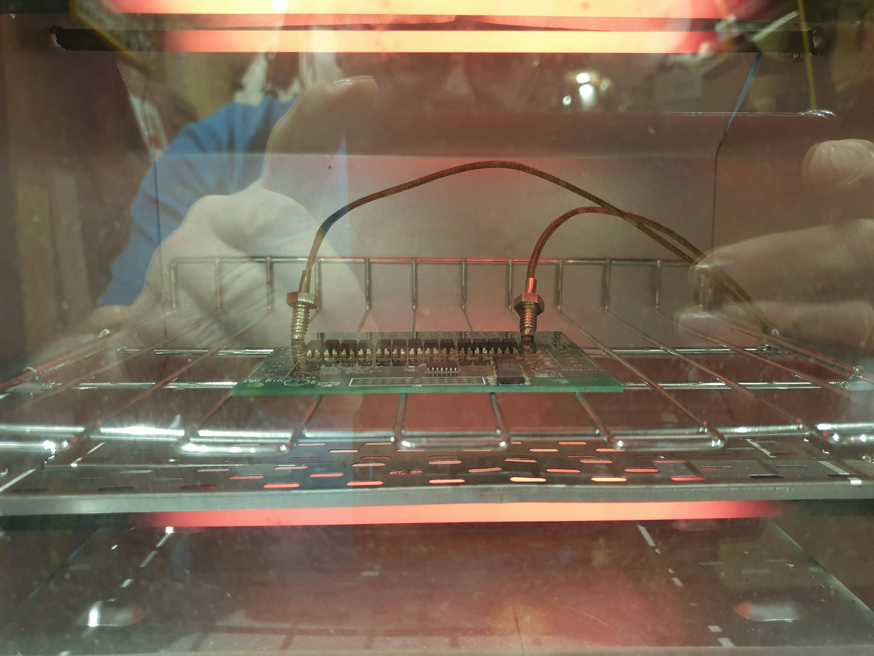
Looking good so far
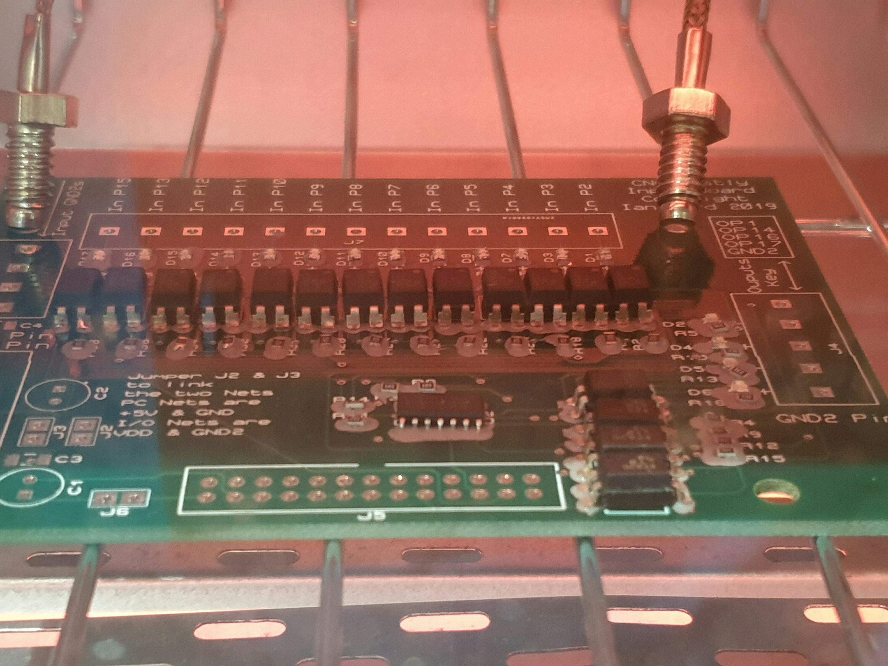
Beginning to flow, a bit too much paste with the benefit of hindsight
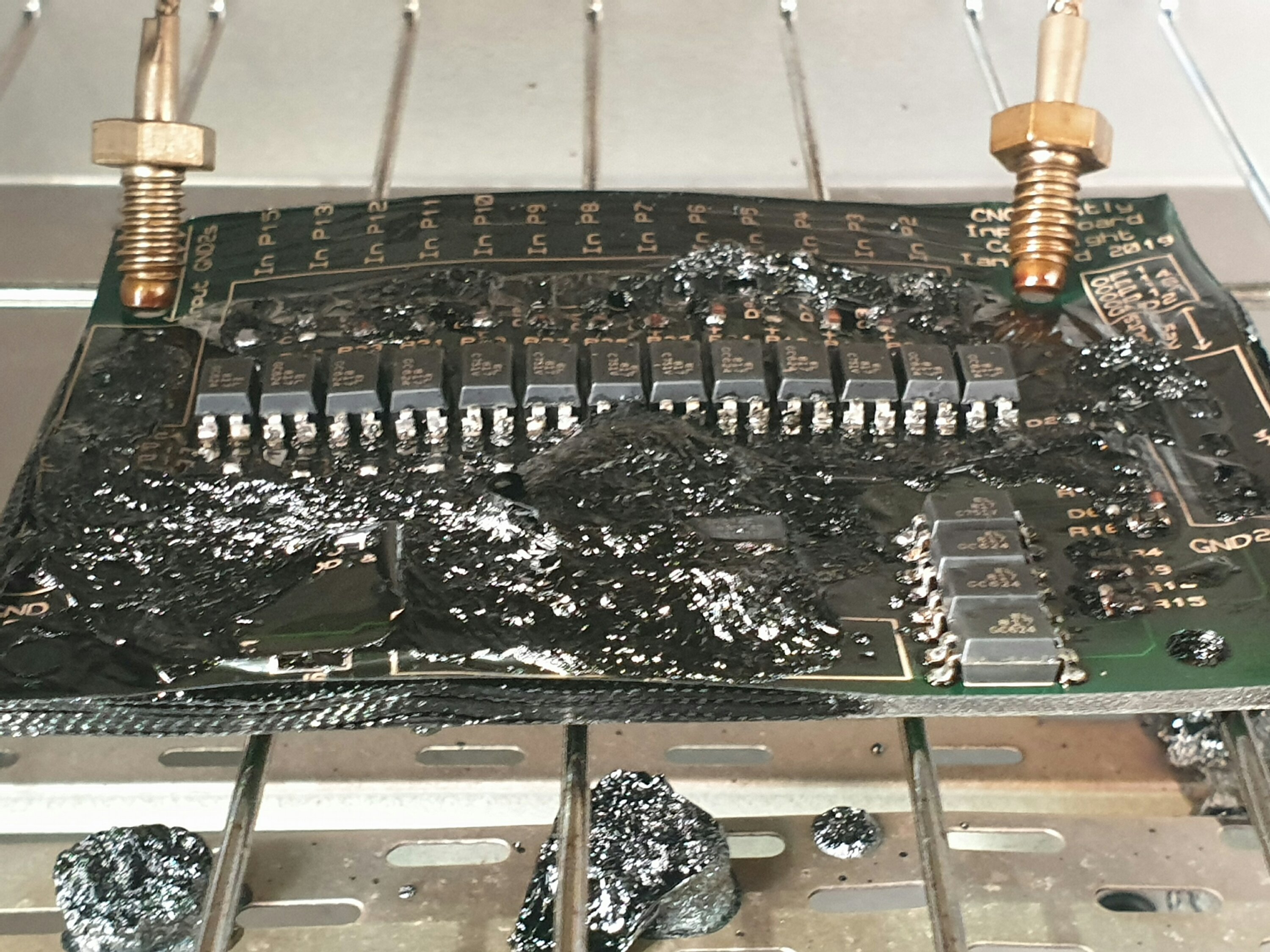
It went to pot very quickly….. The board started to blister at the middle back first but was quickly followed by both edges. The belching smoke was incredible and it only took a few seconds to get to the photo above. Incredibly the optos survived the mess and are all happily working on the first prototype below. I think from this an IR type oven is the way to go. From scratch though it may be better to get a pre made oven. There are a couple of alternatives, the 962 variants on eBay or Amazon or the QS-5100 ones. They look incredibly similar although the latter gets much better reviews but of course is more than twice the cost. The 962 ones can be made good and have a slightly bigger pcb draw, lots of information on the Internet, ho hum, we’ll see.
7/10/2019: The first board is now complete and has passed initial testing. Nothing connected to the SmoothStepper yet, that will come soon I’m sure. The specs on the board are pretty standard. 13 optically isolated inputs, 4 optically isolated outputs, power via pin 26 support, dual power nets supported i.e. controller side and I/O side. These of course can be jumpered together. I have added led indicators on all of the I/O as I like to be able to see when changes occur.
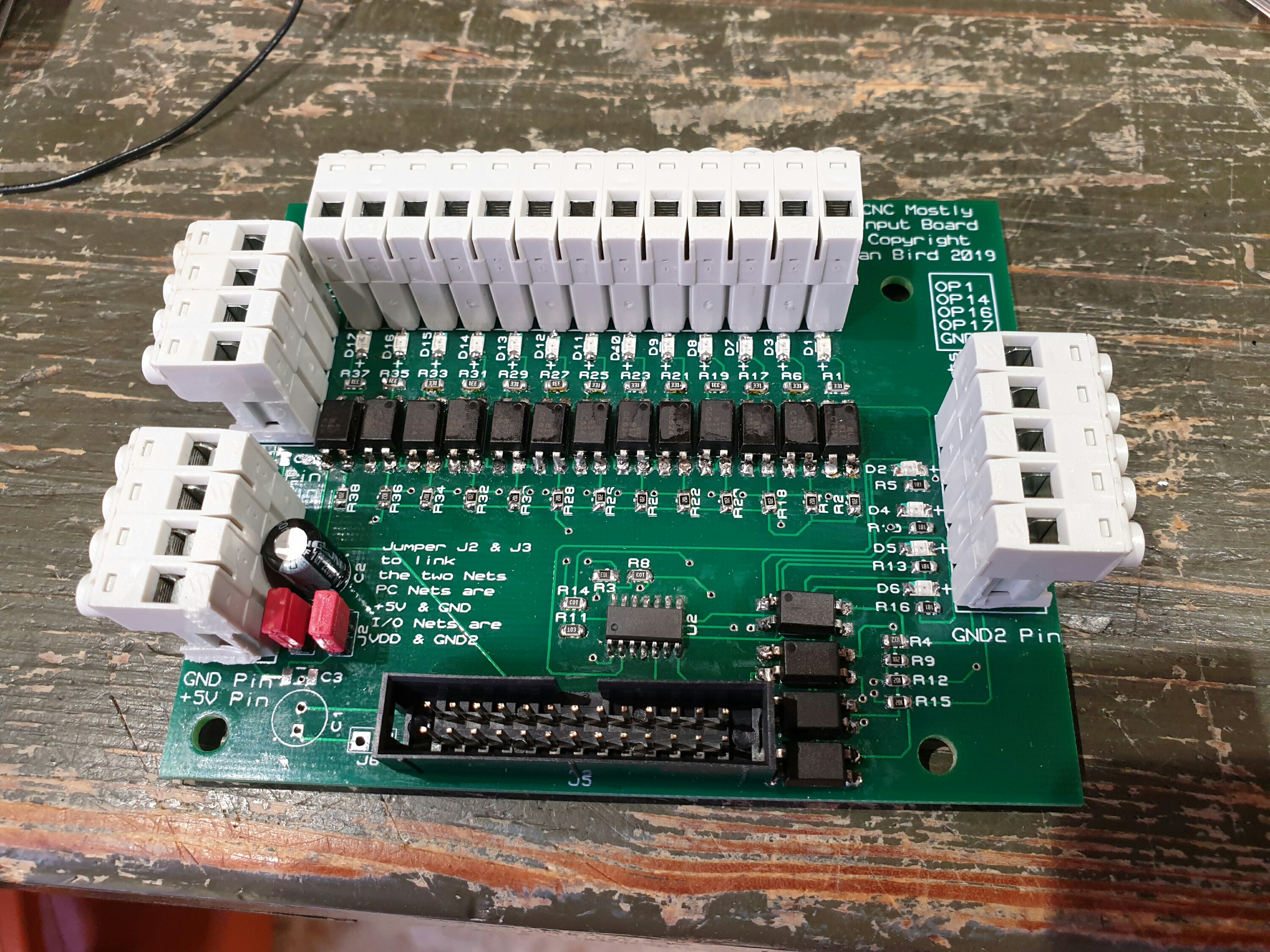
As I have built this I have made numerous tweaks. Most are to component footprints or location but I did realise I had forgotten power LEDs – oops.
16/11/2019: Well well, interesting times. I needed to drill some 13mm holes in some 5mm steel to make a bracket. I managed to drill out to 6mm but then the holes broke through the sides rendering any manual drilling impossible. Since the mill was sort of working manually I thought I would tweak it and use manual g-code to mill the remaining metal out. Ohhh, if it was only that simple.
I was getting close and was trying to set up a pendant when it went very pear shaped, it was spectacularly unspectacular in that the machine just stopped responding to mach3. I still have no idea what went wrong but I never did get mach3 working again. The answer it turned out was to go to Mach4. After lots of reading and fiddling I have now got it working. All motors moving in the correct direction, spindle too and it even rotates. I have everything moving both fast and under controlled feed although I have not worked out what the feed rate is or how to adjust it. Getting there though. More playing around with it tomorrow
27/12/2019: Well, quite a lot has happened over the last few weeks. After messing around with Mach4 I managed to get my brackets drilled using MDI as the control method.
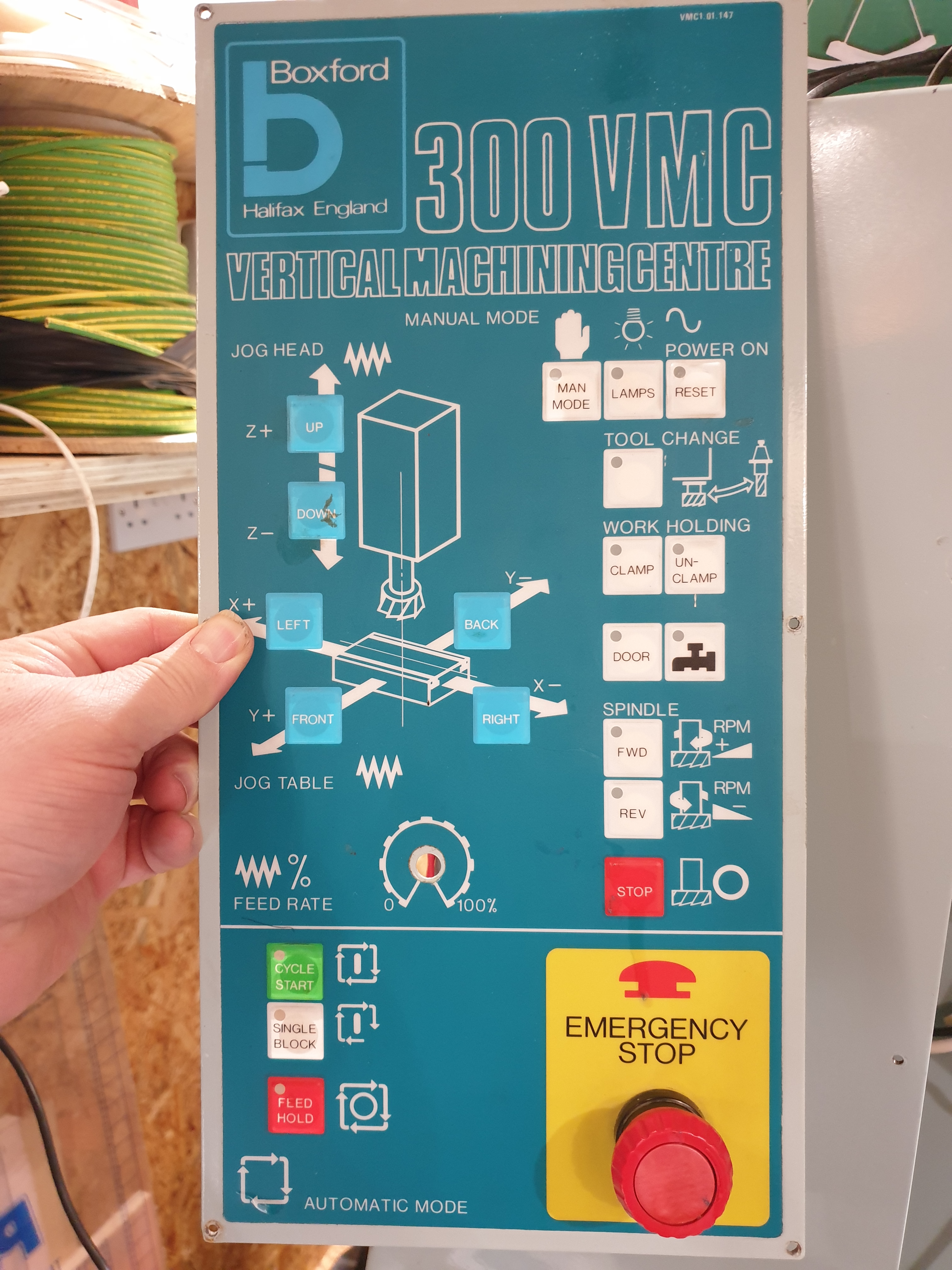
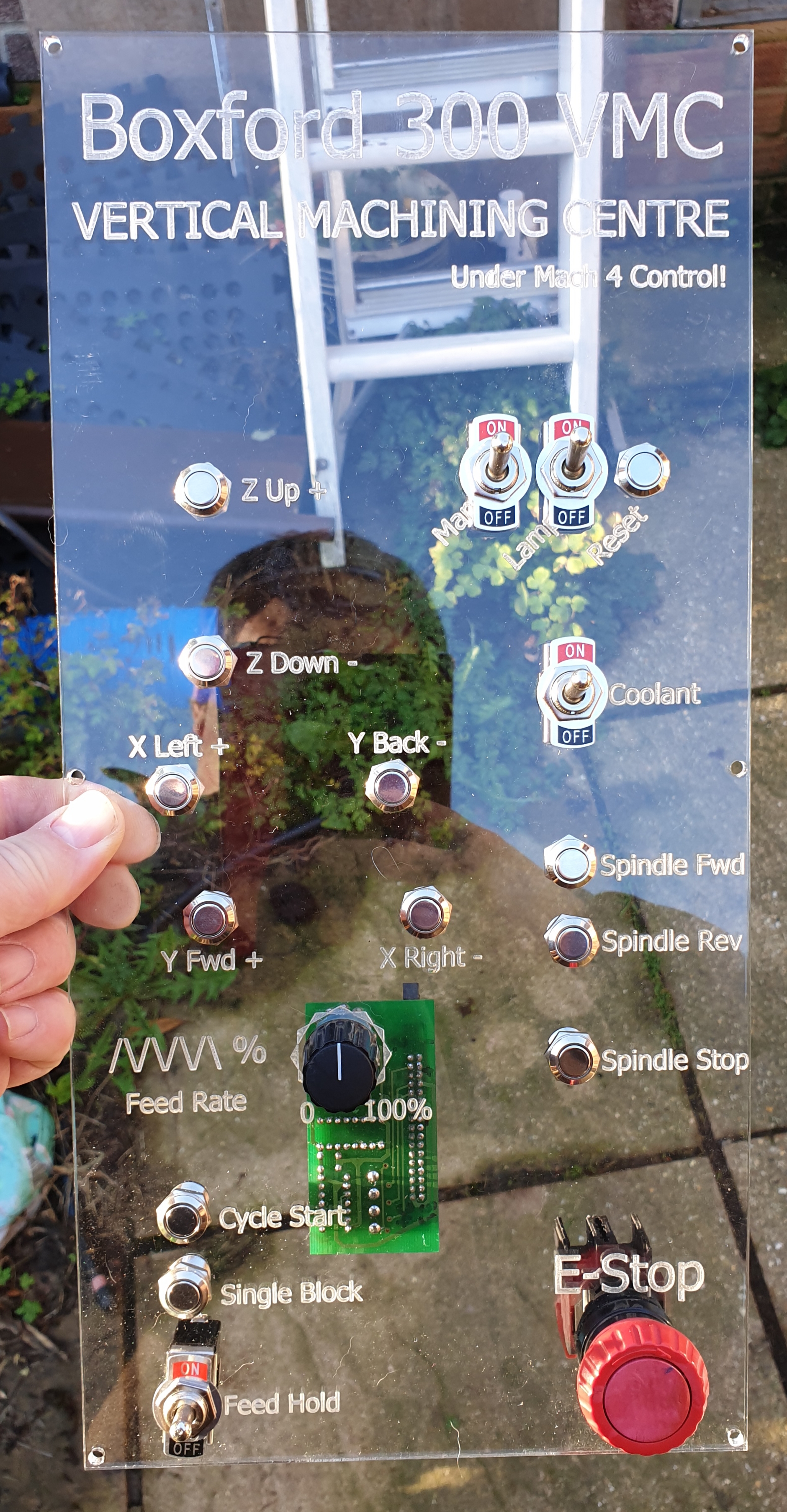
So,what next? It’s time to sort out the front panel and the manual and program controls. I’m going to essentially replicate the original Boxford setup less the controls I don’t need.
On the left is the original and on the right the prototype for its replacement. I will back it with a solid colour like black and light it from all sides with leds. We’ll see.
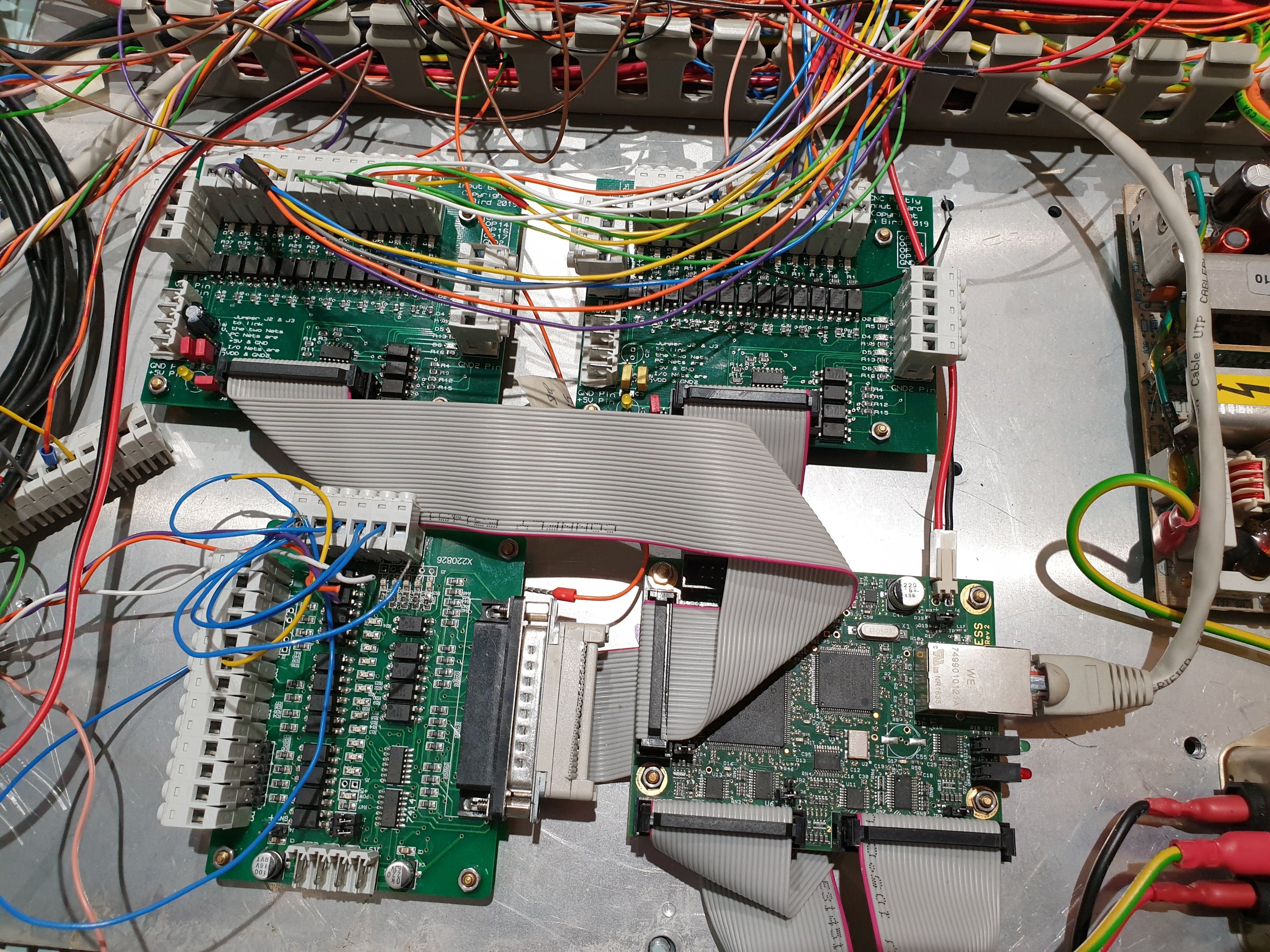
Of course all these manual controls require a lot of inputs, about 19 at the last count. I have now assembled two of my own breakout boards to accommodate these.
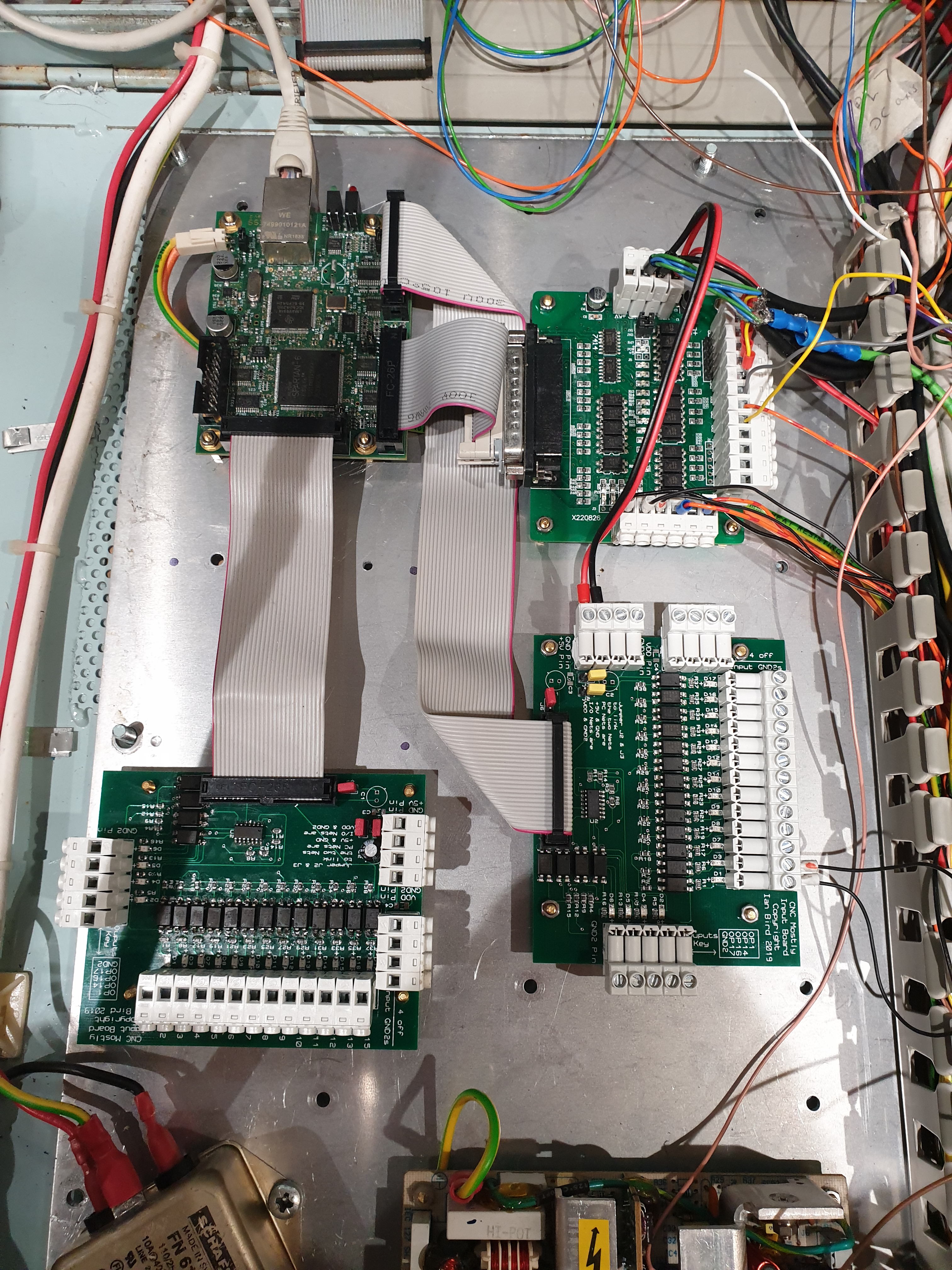
On the top left is the SmoothStepper , top right is an eBay breakout board albeit with the connectors replaced and finally the bottom two are my own mostly input type breakout boards. Whilst the controller side runs at 5v I will be running the input switches etc. at 12 volts. Luckily this is supported by my boards.
Even making these surface mount style boards has become easier with a shiny new QS-5100 reflow oven to solder the dust like components. I am very impressed with its performance and this one didn’t have any faults needing attention post cooking.
11/04/2020: Well, it has been a while hasn’t it. I have not been completely idle and actually have made some significant progress.
It turns out that I have had to move to Mach4. I came out to the garage one day and my setup refused to talk to Mach3 and I could not solve it. Oh dear, this has meant a lot of work however the end result is probably going to be a lot better than sticking with Mach3.
In order to help make the move I decided I needed to move from the actual machine and go onto my workbench. To this end I have removed all the electronics from the computer and SmoothStepper to all the breakout boards. Since all the limit switches and motors were all setup I just left these on the machine and added shorts on the inputs to make it look as though all the switches were there.
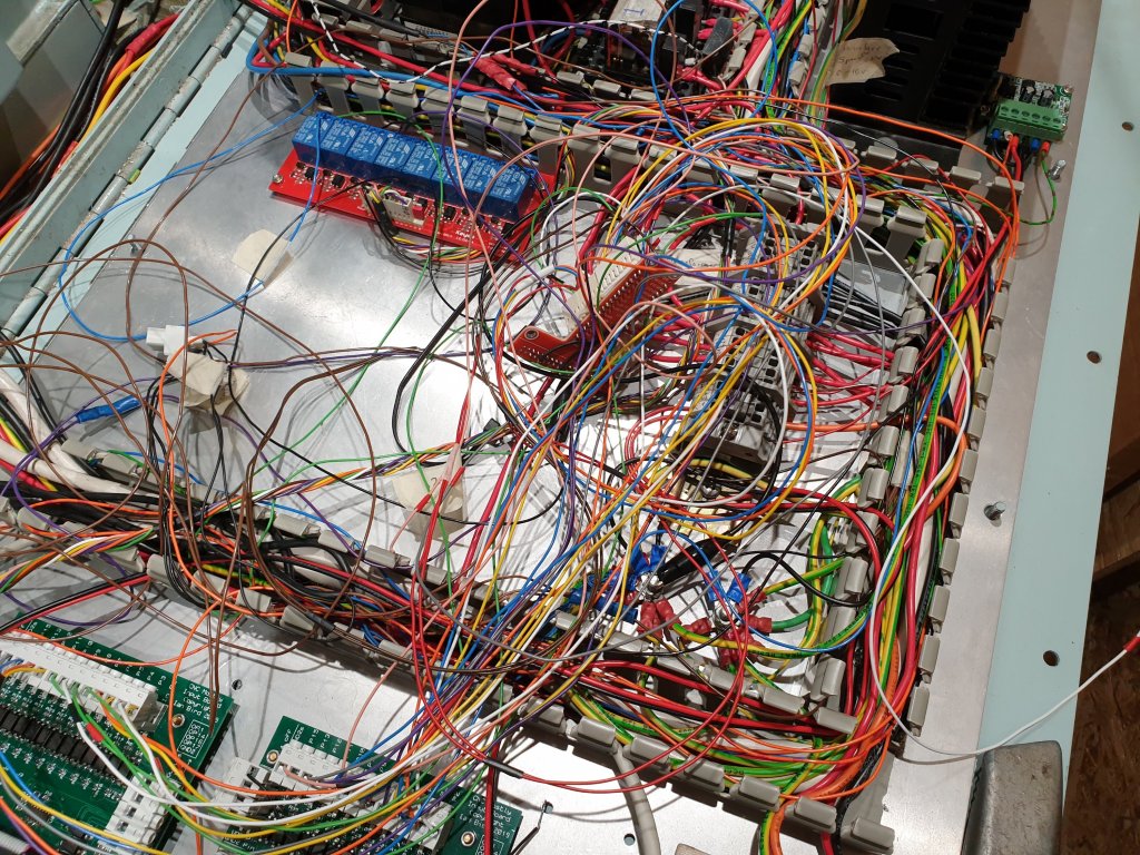
Below you can see a picture of the absolute mess that is my work area at the end of a frustrating but eventually rewarding day.
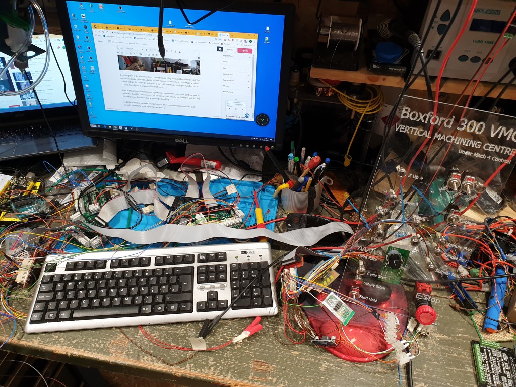
Would you believe it if I told you there was a complete and working Mach4 setup under all the junk! Well, there is.
I have wired in almost all of the inputs on the new panel to match what was there on the old Boxford. I have had to create two additional circuit boards to interface 5v to 12v logic for the MPG and inverted logic i.e. I needed to be able to sink current but the circuit was sourcing it. These both work as planned which is great.
Lua coding is a special kind of headache but a lot of perseverance and Googling has enabled me to get everything I need done so far.
I think the list is impressive.
- Pendant with full functionality installed and working
- Button presses to move X, Y and Z axes
- Manual control of coolant which also works with G code control
- Spindle forward button, multiple presses increases the speed
- Spindle reverse button, multiple presses increases the speed
- Spindle Stop button which also resets the speed to 0
- Feed rate override between 0 and 250% using the original Boxford rotary control
- Cycle start button
- Single Block button
- Feed hold button
- E-Stop
The only thing is I have run out of inputs on the ESS board meaning something may have to go back to screen only control, we’ll see.
It turns out Easter holidays and the current Covid-19 lock down bode well for both gardening and time in the garage.
26/4/2020: It was big weekend for me and the Boxford. The mess that was my development on the bench with Mach4 has migrated on to the machine. Initially it was an even bigger mess but after a few hours and a very stiff back we are getting closer.
And a wee bit later……

On the original wiring the communication between the original front panel and electronics was by a 40 pin ribbon cable. I decided to reuse this and the red T shaped connector adapter originally started life as a Raspberry Pi expansion connector. I removed the pins and added proper connectors and with a little cutting and soldering we have a nice connector block.
I have run into one problem with the mpg though. When I select an axis and speed then turn the mpg the motors just clonk a bit. The readouts update as you would expect but the real world just doesn’t live up to expectations. Some investigation with the scope reveals that the pulse length being sent to the motor driver is about 5 or 6 times longer using the mpg than when jogging in any other way. The jury is out as to the cause of this and I have no idea how to fix it.
2/9/2020: I have spent a little more time looking at the mill and its various little foibles. This has been driven a little by a friend who needs a runner made for a window. So, motivation sorted, just the machine, software and skill to aquire and hone. I used MeshCAM to convert the stl file to gcode and started to feed it to Mach4. On the whole things could have been worse. A poor choice of cutter, speeds and feeds means I have now mastered cold welding / smearing aluminium to HSS. Oh well, Cet la vie. This is still a work in progress.
On the up side I looked again at the MPG and found the setting in Mach4 which was stopping it working. It turns out that I had not set the acceleration and speed values. Fix these and instant success, yippee.
29/9/2020: I have succeeded in making the small runner component mentioned above now. A better choice of a two flute cutter and feed rate and cutting depth sorted it.
My next project has been to update the feed rate override switch so it outputs Gray code rather than a weird inverted binary coded decimal which Boxford had designed. This is making progress and the story so far is in the PCB section.
More soon
